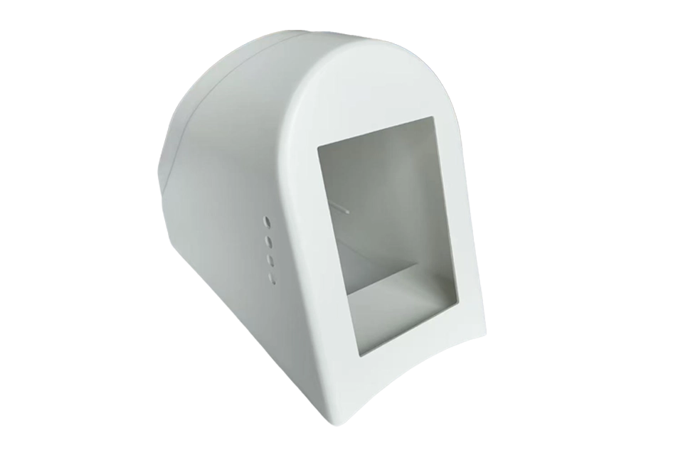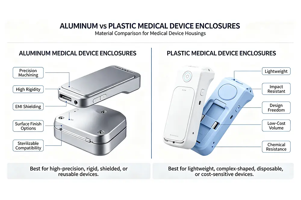
A mobile medical or aesthetic device is more than an outer plastic housing. Behind the enclosure, there is often a structural frame that carries the equipment, controls the center of gravity, provides mounting points, and determines how easily the final housing can be assembled.
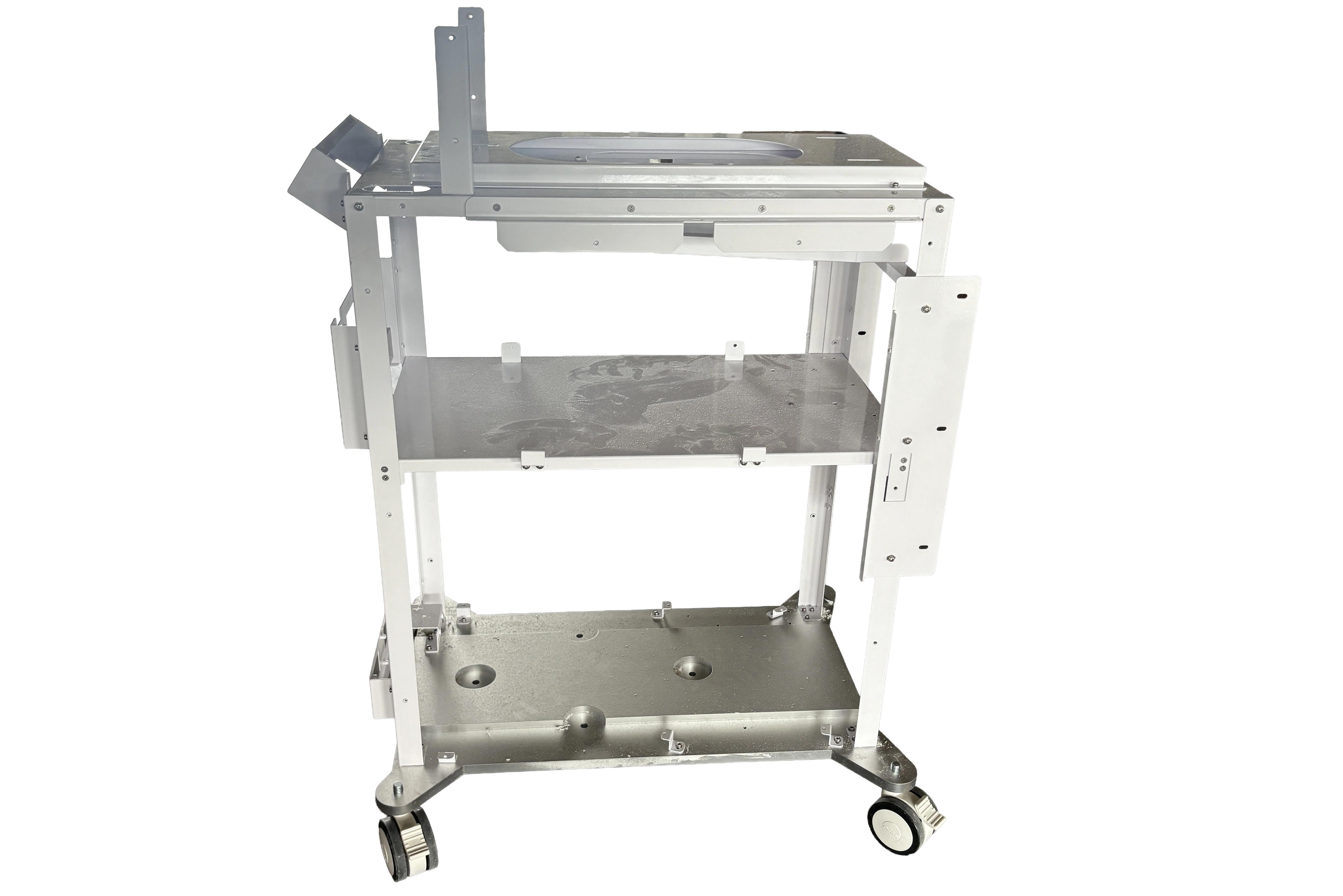
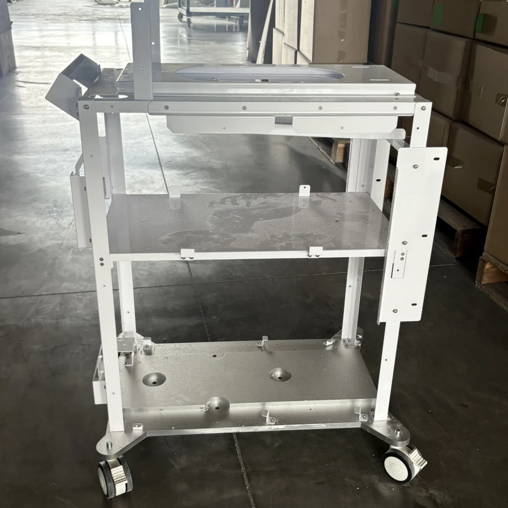
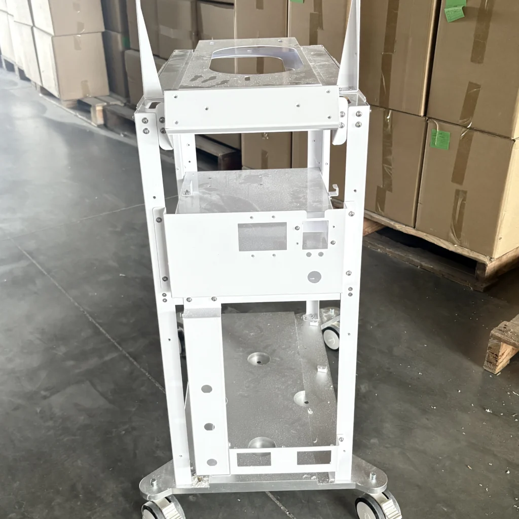
For this project, our customer needed a custom medical device cart frame for a mobile weight-loss device. The frame would become the internal load-bearing structure of the equipment cart, supporting the power supply, circuit boards, water tank, main device head, and other components. A plastic exterior housing would later cover the metal structure, while lockable casters would make the finished system mobile.
At Zhongrongda, we manufactured the frame using sheet metal cutting, bending, welding, bolted assembly, and white powder coating. The project required more than simply producing individual metal parts. Our engineering team had to consider structural rigidity, column perpendicularity, mounting-hole alignment, serviceability, caster positioning, and the fit between the metal frame and the outer plastic enclosure.
The project was produced in small batches and has now entered mass production.
For customers developing medical and aesthetic equipment, this type of internal structure can be developed alongside the enclosure as part of a complete Medical Device Enclosure solution.
Project Overview
| Item | Project Specification |
|---|---|
| Industry | Medical & Aesthetic Equipment |
| Application | Mobile weight-loss device cart |
| Country / Region | Wuhan, China |
| Material | Galvanized steel / cold-rolled steel / aluminum sheet |
| Dimensions | 480 × 680 × 950 mm |
| Surface Finish | White electrostatic powder coating |
| Tolerance | Mounting-hole positions ±0.2 mm; structural alignment controlled according to assembly requirements |
| Manufacturing Process | Laser cutting, sheet metal bending, welding, bolted assembly, powder coating |
| Quantity | Small batch, followed by mass production |
| Lead Time | Project-dependent; confirmed after drawing and quantity review |
Customer Requirements
The customer needed a rigid internal chassis that could support multiple equipment modules while remaining compact enough to fit inside the finished cart.
The frame consisted of three load-bearing platforms. Different components could be installed on different levels, while additional openings were required for cable routing and equipment positioning.
The main structural requirements were:
- High load-bearing capacity without significant deformation.
- Three levels of equipment mounting platforms.
- Vertical support columns with controlled perpendicularity.
- Accurate mounting-hole positions for components and subassemblies.
- Dedicated mounting positions for the main device head.
- Caster mounting holes at the bottom of the frame.
- Sufficient cable-routing openings throughout the structure.
- Easy removal and installation of individual shelves.
- Compatibility with the external plastic decorative housing.
- Smooth edges without burrs or sharp corners.
- White powder-coated surface for corrosion resistance and appearance.
From a purchasing perspective, the customer was not simply buying laser-cut and bent sheet metal. They needed a finished structural assembly that could be integrated into a complete mobile device.
That distinction influenced how we approached the project.
Manufacturing Challenges
1. Maintaining Structural Rigidity
The frame had to carry multiple equipment modules distributed across three levels. A weak structure could deform under load and affect the alignment of components or the appearance of the external enclosure.
Our engineering team therefore considered the relationship between sheet thickness, bending geometry, support positions, welding locations, and load distribution during the design review.
The objective was to create a rigid structure without unnecessarily increasing material usage or weight.
2. Controlling Column Perpendicularity
The vertical columns were particularly important because the plastic exterior housing would later be installed around the metal frame.
If the columns deviated significantly from their intended position, the outer housing could experience interference during assembly.
For this reason, perpendicularity was treated as an assembly-critical characteristic rather than simply a cosmetic dimension.
3. Aligning Multiple Levels
The three mounting platforms needed to maintain consistent positioning relative to the vertical structure.
Misaligned mounting holes could make component installation difficult, especially when several parts needed to be fastened across different levels.
The mounting-hole positions were therefore controlled to approximately ±0.2 mm according to the project requirements.
4. Managing the Center of Gravity
Because the finished product was a mobile cart, structural strength alone was not enough.
The positions of the equipment, water tank, main device head, and other components had to work with the caster locations to create a stable overall system.
The frame therefore had to provide a practical structural foundation for stable movement without unnecessarily increasing the footprint.
5. Preparing for Powder Coating
The frame required a white powder-coated finish. Before coating, we had to consider edge conditions, weld areas, surface cleanliness, and the locations of mounting interfaces.
A good powder-coated finish starts with manufacturing preparation—not simply with the coating process itself.
Our Engineering Solution
At Zhongrongda, we approached this project as an assembly engineering problem, rather than treating each sheet-metal component independently.
DFM Review
Our engineering team reviewed the structure before production to identify potential problems related to bending, welding, assembly, and enclosure integration.
We paid particular attention to:
- Bend locations and bend accessibility.
- Welding sequence.
- Hole positioning.
- Shelf installation and removal.
- Caster mounting.
- Cable-routing openings.
- Plastic enclosure clearance.
- Overall structural alignment.
For customers developing a new device, this type of early DFM review can reduce unnecessary modifications after the first prototype.
Welding and Fixture Control
Welding can introduce heat-related distortion, especially in larger assembled structures.
We therefore considered the welding sequence and positioning method to maintain the relationship between the columns and mounting platforms.
Where necessary, fixtures can be used to hold components in their intended positions during welding.
This is particularly important when the finished frame has to fit inside a molded plastic enclosure.
Hole and Feature Positioning
The mounting holes were designed around the actual assembly requirements rather than treated as independent cutting features.
This included:
- Component mounting holes.
- Caster mounting holes.
- Cable-routing openings.
- Device positioning features.
- Main device-head mounting locations.
This approach helped ensure that the frame could function as the foundation for the complete equipment assembly.
Structural and Dimensional Inspection
After fabrication, we checked critical dimensions and assembly interfaces before the frame moved to final finishing.
Our general manufacturing capability supports both metal and plastic enclosure projects, allowing customers to combine structural frames with external housings through our broader Manufacturing capabilities.
Manufacturing Process
The manufacturing process for this project followed a controlled sequence:
1. DFM Review
We reviewed the drawings and structural requirements before production.
2. Programming
Laser-cutting programs were prepared according to the approved drawings.
3. Material Preparation
The required galvanized steel, cold-rolled steel, and aluminum sheet materials were prepared according to the project specification.
4. Laser Cutting
Sheet materials were laser cut to create the required structural components, mounting plates, cable openings, and connection features.
5. Sheet Metal Bending
The cut components were formed according to the required dimensions and bending geometry.
6. Welding
The structural components were positioned and welded into the required frame configuration.
7. Deburring
Sharp edges and burrs were removed to improve handling safety and assembly quality.
8. Bolted Assembly
The multi-level support structure was assembled using bolts where removable installation was required.
9. Surface Finishing
The completed frame received white electrostatic powder coating for its final appearance and corrosion protection.
10. Inspection and Packaging
The finished assemblies were inspected, protected against surface damage, and prepared for shipment and subsequent equipment assembly.
For projects requiring an initial prototype before production, our Rapid Prototyping service can also be used to verify fit, structure, and assembly before committing to larger quantities.
Quality Inspection
Quality control focused on the dimensions and interfaces that could affect final equipment assembly.
Our inspection process can include:
Caliper inspection
Used for general dimensional checks, sheet-metal features, and accessible structural dimensions.
Micrometer inspection
Used where more precise dimensional verification is required.
Height gauge inspection
Useful for checking height-related features and relative positioning on structural assemblies.
CMM inspection
For projects requiring more comprehensive dimensional verification, CMM inspection can be used to evaluate critical locations and geometric relationships.
First Article Inspection
For a new project, the first completed unit can be inspected against the approved drawings before proceeding with the production batch.
Final Inspection
Before shipment, we verify key dimensions, hole positions, structural assembly, surface finish, burr condition, and other customer-defined requirements.
Our quality system is supported by ISO 9001 and ISO 13485 certification, providing a documented foundation for quality management in medical-related manufacturing projects.
Final Results
The completed frame provided the internal structural foundation for the mobile weight-loss device.
The finished assembly delivered:
- Three load-bearing equipment levels.
- Stable vertical support.
- Accurate component mounting locations.
- Dedicated cable-routing openings.
- Caster mounting provisions.
- A white powder-coated appearance.
- Removable structural components for easier assembly and service.
- Clearance for installation of the external plastic housing.
Most importantly, the project moved beyond prototype development into mass production.
This is an important stage for equipment manufacturers. A prototype frame can demonstrate basic feasibility, but production requires repeatable fabrication, stable assembly, controlled dimensions, and consistent finishing.
Our role was therefore not limited to manufacturing individual sheet-metal parts. We supported the transition from structural concept to a repeatable production assembly.
Why Choose Zhongrongda
Engineering Support
Our engineering team works with customers to review drawings, manufacturing methods, assembly interfaces, and production requirements before fabrication.
Fast Quotation
Send us your drawings, 3D files, dimensions, material requirements, or even an initial concept. We can review the available information and identify what is needed for quotation.
Rapid Prototyping
When fit and assembly need to be verified first, we can support prototype development before small-batch production.
Small Batch Manufacturing
Not every medical or aesthetic equipment project immediately requires high-volume production. We support small-batch manufacturing as products move through development and commercialization.
Integrated Enclosure Manufacturing
An internal metal frame often works together with an external plastic enclosure. Our experience across equipment enclosure projects allows us to consider the structural frame and exterior housing as part of the same product architecture.
You can explore our Case Studies to see how we approach different equipment enclosure and manufacturing projects.
Quality Management
Our manufacturing operations are supported by ISO 9001 and ISO 13485, with quality inspection procedures applied according to project requirements.
NDA and Confidentiality
For customers developing new medical, aesthetic, laboratory, or industrial equipment, protecting drawings and product information is essential. NDA arrangements can be discussed before project information is shared.
FAQ
1. What is the MOQ for a custom medical device cart frame?
MOQ depends on the frame design, material, manufacturing process, and production requirements. We can support prototype development, small-batch production, and larger production quantities.
2. How long does manufacturing take?
Lead time depends on drawing complexity, material availability, quantity, surface treatment, and assembly requirements. After reviewing your drawings, our engineering team can provide a project-specific schedule.
3. What tolerance can you achieve for sheet-metal frames?
Tolerance depends on the material, thickness, cutting, bending, welding, and the specific feature. For this project, critical mounting-hole positions were controlled to approximately ±0.2 mm.
4. What materials can you use for medical equipment frames?
Common options include cold-rolled steel, galvanized steel, stainless steel, and aluminum alloys. Material selection depends on structural requirements, weight, corrosion resistance, appearance, and application.
5. What surface finishes are available?
Depending on the project, options can include powder coating, painting, anodizing, plating, and other specified finishes. For this project, we used white electrostatic powder coating.
6. Can you manufacture an internal chassis and external enclosure together?
Yes. An internal metal frame can be developed alongside an external plastic or metal enclosure. This can help address mounting, clearance, cable routing, and assembly requirements earlier in the product development process.
7. Can you sign an NDA before reviewing my drawings?
Yes. NDA requirements can be discussed before confidential drawings, 3D models, specifications, or other proprietary information are shared.
8. Do you support rapid prototyping?
Yes. We support prototype development for equipment structures and enclosures so customers can verify fit, function, assembly, and appearance before moving into production.
9. Do you support small-batch manufacturing?
Yes. Small-batch manufacturing is available for equipment manufacturers that are validating a new product, completing pilot production, or gradually increasing production volume.
10. Can you manufacture custom medical device enclosures?
Yes. Zhongrongda specializes in custom equipment enclosure manufacturing, including medical device enclosures, laboratory equipment enclosures, medical robot enclosures, diagnostic equipment enclosures, and related structural components.
CTA
Need a reliable CNC machining and manufacturing partner for your next project?
Upload your drawings today and our engineering team will provide a free DFM review and quotation within 24 hours.
Whether you need a custom medical device cart frame, internal equipment chassis, sheet-metal structure, plastic enclosure, prototype, or small-batch production, we can review your requirements and recommend a practical manufacturing approach.
Contact our engineering team to discuss your next project.